Reflow Oven Controller
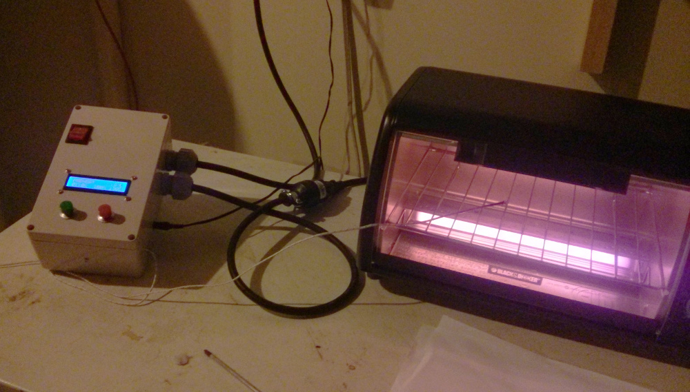
This Arduino based controller turns an ordinary toaster oven into an oven for reflow soldering.

Reflow soldering is an electronics assembly process that is inexpensive and commonly used in automated electronics assembly, but it is a process that can also be used to assemble electronics efficiently at home. Many people have had success simply heating boards in a conventional oven or on a skillet, but consistent and reliable soldering requires very precise control over the temperature and very careful timing, which these methods simply do not provide. To this end, I created a controller that turns an ordinary toaster oven into an oven that can be used for reflow soldering.
Operation
The reflow controller is plugged into an outlet and the oven is plugged into the socket on the controller. The thermocouple connected to the controller is placed inside the oven, preferably on the board being reflowed. When the green button is pressed, the process starts. The procedure that the controller follows depends on the reflow profile that is programmed into it, but it generally resembles the following procedure:
- The oven is heated to the soak temperature and held. This temperature is maintained for a period of time to activate the flux.
- The oven is quickly ramped up from the soak temperature to the peak reflow temperature and this temperature is very briefly held.
- The oven is cooled back down to room temperature
If all went well during the above procedure, the solder will have flowed onto the components and permanently attached them to the PCB.
Technical Overview
Hardware Description
The controller is based on an Arduino Duemilanove, which was selected because of its relatively low cost, built in USB port, and extensive 3rd party library support. The controls on the reflow controller are simply a start button and a stop button. A 16x2 character LCD is used to display status information. A solid state relay is used to switch the heating elements on and off and a K-type thermocouple is used for temperature sensing. The oven temperature is controlled by a PID loop that monitors the thermocouple temperature and modulates the duty cycle of the heating element accordingly.
I intentionally avoided modifying the toaster oven directly. Leaving the oven unmodified leaves the oven’s temperature controls operational, which is an extra layer of safety that prevents accidental overheating. Instead of wiring the SSR into the heating elements directly, I decided to design the controller so that the oven could simply plug into it. This not only means that the controller works with an unmodified oven, but it also makes it fairly flexible and makes it possible to use the controller with other devices. I’ve had success using this controller to control the temperature of a simple dough proofing oven.

The inside of the controller. The potentiometer controls the LCD contrast.
Parts List
- Maxim 6675 Thermocouple to digital converter module
- Clone HD44780 16x2 LCD
- SSR-25DA Solid state relay
- A plastic project box (eBay sourced)
- Arduino Duemilanove compatible clone
- 14 Ga three conductor braided mains cable
- Male plug end
- Female plug end
- 2x Enclosure mounted cable strain reliefs for the mains cables
- Crimp-on hoop connectors
- Arduino protoshield
Additionally, I used a few different connectors for the display and buttons. The current drawn by the connected devices is relatively small, so almost anything with good retention would work. I used dupont-style connectors bacause I happened to have them on hand at the time, but I do not recommend using them in this applications as they don’t have much retention force and could come loose.
Software Overview
Safety Features

Testing the safety features. Oops!
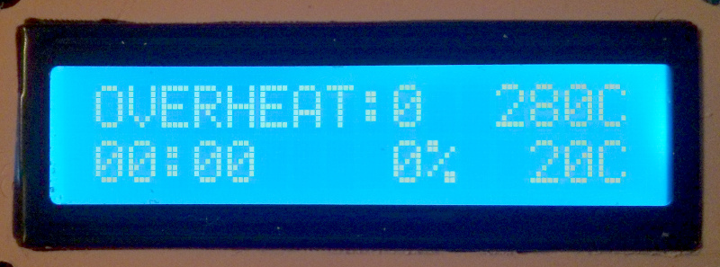
Since this is a device that could potentially burn someone’s house down, I put some effort into including a few important safety features. The firmware can detect a variety of fault conditions, including overheating, a disconnected thermocouple or a failure to reach a target temperature in a reasonable amount of time. The latter is particularly important in the case of damaged or inadvertently removed thermocouple as it could result in the PID control going open loop and causing the heating elements to stay on constantly. In the case of a fault, the heating element is switched off, an error message is printed to the display and the program is halted by placing the processor in an infinite loop.
However, this does not necessarily protect the device from a program hang or crash. In this case, a program hang is of particular concern since the firmware uses cooperative multitasking. To avoid having a programming error burn my house down, I made use of the on-chip watchdog timer. If the timer is not reset every 500ms, the following code is executed:
    ISR(WDT_vect){
        //WDT Expired, All pins become inputs, pullups disabled
        DDRB = 0;
        DDRC = 0;
        DDRD = 0;
        PORTB = 0;
        PORTC = 0;
        PORTD = 0;
        //Work-around for questionable bootloader code
        //System reset flag is not cleared by the booloader
        wdt_disable();
        //"reset" the MCU -- works around needing bootloader modification
        asm volatile("jmp 0");
        //This is only executed if the MCU does not get reset
        while(1){}
    }
This code puts all I/O pins into a high impedance state (shutting off the heating element in the process) and attempts to reset the microcontroller. If, for some reason, resetting the microcontroller fails, it will simply spin until the user manually resets the microcontroller.
When I intially wrote the watch dog timer interrupt code, I discovered that my Arduino board would get stuck in an infinite reset loop when a WDT reset occurred. After some research, I discovered that some versions of the Arduino bootloader did not clear the WDRF (Watchdog System Reset Flag) bit on startup, resulting in the watchdog timer resetting the chip again after the default timeout of 16ms. Unfortunately, there was no easy way to correct that without modifying the bootloader, so I instead decided to work around the issue by disabling the WDT inside of the interrupt subroutine and “reset” the chip by jumping to address 0. This isn’t optimal for a number of reasons, but it does provide some protection from programming errors.
PWM
slow_pwm.h
The ATMEGA328P that the Arduino board is based around has a built in wave form generator that can generate a pulse width modulated output. This PWM output is typically how you’d control the amount of power going to a load such as a heating element. However, the frequency with which a solid state relay can be switched on and off is limited and the included analogWrite() function uses a frequency of 490Hz, which is much too fast.
The ATMEGA328P itself has a fairly flexible waveform generator, and it would have been possible to use it in the phase and frequency correct mode to achieve the very low frequency PWM I was looking for, however, I decided to preform the pulse width modulation in software instead. This was because I had already decided upon a cooperative multitasking scheme for preforming all of the tasks the controller was responsible for and the PWM output only needed to run at a very low frequency (approximately 10Hz in this case). For this reason, I decided that a software implementation would be simpler, more flexible and more portable.
PID Control
pid.h
This controller uses a fairly simple PID implementation, the PID loop is updated inside of the main control loop of the oven and the PID constants are defined in the code. This does make tuning the PID controller a little more difficult as there is no way to adjust the PID constants without reuploading the program, but it keeps the code very simple. The code for the PID loop was based on the code in this series of blog posts. Some minor modifications were made to make it possible use a variable time step rather than a fixed time step as the code is called with variable latency.
If I were to revisit this project I’d consider using one of the many PID libraries available for Arduino now. The PID algorithm used by some 3D printer firmware even has the ability to self tune, which would be a fantastic feature to have in this application.
Reflow profile
reflow_main.ino
The reflow profile is simply hard coded into the program. This works perfectly fine for my uses, but it might be nice to to have multiple profiles in the future. This could be accomplished by using a strategy pattern where each reflow profile is contained within a separate class.
    //PREHEAT: 2C/ s up to 150C
    if (phase == PREHEAT){
        setpoint += PREHEAT_RATE * dt;
        if (temperature >= 150){
            phase = SOAK;
        }else if(setpoint >= 150){
            setpoint = 150;
        }
    }else if(phase == SOAK){
        //SOAK: Ramp to 200 over 60s
        //we only increment the setpoint here
        setpoint += SOAK_RATE * dt;
        if (setpoint > 200){
            phase = RAMP_UP;
        }
    }else if(phase == RAMP_UP){
        //REFLOW: 3C/s to 255C
        setpoint += RAMP_RATE * dt;
        if (setpoint > 255){setpoint = 255;}
        if (temperature >= 250){
            phase = REFLOW;
            reflow_start = millis();
        }
    }

    ...
Each task the controller needs to preform is ether preformed inside the main loop itself, is implemented as a function that is called periodically, or is an object with an update() function that is called by the main loop. The smaller unis of work, like reading the temperature sensor and updating the LCD are preformed in the main loop itself, while the more complicated tasks are divided into separate functions.
